Tuesday, September 29, 2015

Technologies Used in Multiplexing

Sending email is a commonplace occurrence in our daily life. When you send an email to a friend in another city, it will firstly join up with other messages being transmitted in your city, and then get dropped off at the correct destination in the correct city. How do all of these messages get to join together and be transmitted without getting mixed up? This process is achieved through the use of multiplmexing technology, which is a method that combines multiple analog message signals or digital data streams into one signal over a shared medium. Actually, multiplexing is widely used in many telecommunications applications. This article will introduce multiplexing technology from the aspect of common technologies used in multiplexing.
Optical multiplexing filter is an essential component in multiplexing technology, which is a physical device that combines each wavelength with other wavelengths (as shown in the following figure). Many technologies are applied in multiplexing, including thin-film filter (TFF), fiber bragg grating (FBG), arrayed waveguide grating (AWG) and interleaver, periodic filter, and frequency slicer.
filter
TFF
Optical TFF typically consists of multiple alternating layers of high- and low-refractive-index material deposited on a glass or polymer substrate. This substrate is made to let only photons of a specific wavelength pass through, while all others are reflected.
FBG
A bragg grating is made of a small section of fiber that has been modified by exposure to ultraviolet radiation to create periodic variations in the refractive index of the fiber. And the process of creating periodic variations will generate wavelength-specific dielectric mirrors. Thus, the FBG can reflect particular wavelengths of light and transmit all others.
AWG
AWG devices can multiplex a large number of wavelengths into a single optical fiber. These devices are designed on the fundamental principle of optics that light waves of different wavelengths interfere linearly with each other. That’ to say, if each channel in an optical communication network makes use of light of a slightly different wavelength, then the light from a large number of these channels can be carried by a single optical fiber.
Interleaver, Periodic filter, and Frequency Slicer
Interleaver, periodic filter and frequency slicer are often used together to perform the function of multiplexing. The following figure shows how interleaver, periodic filter and frequency slicer work together to make a multiplexer device. Periodic filter is in stage 1, which is an AWG. Stage 2 represents the frequency slicer which is another AWG. The interleaver is at the output part, which is provided by six bragg gratings. Six wavelengths (λ) are received at stage 1 which breaks the wavelengths down into odd and even wavelengths. Then the odd and even wavelengths go to stage 2 respectively. Finally, they are delivered by the interleaver in the form of six discrete, interference-free optical channels.
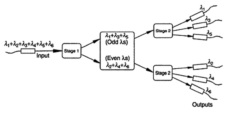
interleaver, periodic filter and frequency slicer
All in all, the usual goal of multiplexing is to enable signals to be transmitted more efficiently over a given communication channel rather than save bandwidth. Nowadays, the most popular multiplexing technology is wavelength division multiplex (WDM), which can be divided into coarse wavelength division multiplexing (CWDM) and dense wavelength division multiplexing (DWDM). It is hoped that multiplexing technology would offer significant gains in bandwidth efficiency.
Originally published at www.fiber-optical-networking.com/

Tuesday, September 22, 2015

Things You Need to Know About MTP/MPO Harness Cable

MTP/MPO harness cable, also called MTP/MPO breakout cable or MTP/MPO fan-out cable, is a fiber optic cable terminated with MTP/MPO connectors on one end and MTP/MPO/LC/FC/SC/ST/MTRJ connectors (generally MTP to LC) on the other end (as shown in the following figure). In addition to its definition, here are something you also need to know about MTP/MPO harness cable.
MTP(MPO) harnesses cable
What Is MTP/MPO Connector
As a kind of multi-fiber connector, the MTP/MPO connector is most commonly used for 12 or 24 fibers in a single connector pushing up to and beyond 100Gbps data transmission. Thus it satisfies the huge demand for more bandwidth and more space efficiency of data centers and ever-expanding server clusters. MTP/MPO connectors are paving the way for increased data transmission speeds and rack density.
Though MTP and MPO are literally different from each other, they are often used interchangeably. The MPO connector is a multi-fiber connector that is defined by IEC-61754-7, and the MTP is a registered trade mark of US Conec (a leader in providing passive components for high density optical interconnects), which identifies a specific brand of the MPO style connector.
Common Types of MTP/MPO Harness Cable
As mentioned above, the connectors on each end of the fiber cable may be the same or not. Thus, the MTP/MPO harness cable is usually divided into MPO/MTP-MPO/MTP harness cable, MPO/MTP-Secure Keyed LC harness cable and MPO/MTP-Standard LC/FC/SC/ST/MTRJ harness cable. In the MPO/MTP-Secure Keyed LC harness cable, the secure keyed LC connector provides a quick, simple termination method, featuring a pre-installed cleaved fiber with an index-matching splice element, and a precision factory pre-polished zirconia ceramic ferrule.
Differences Between MTP/MPO Harness Cable and MTP/MPO Trunk Cable
MTP/MPO harness cables and MTP/MPO trunk cables are two common kinds of MTP/MPO fiber cables. They differ from each other in such aspects as function and application.
MTP/MPO harness cables are designed for high density applications requiring high performance and speedy installation. Harness cables provide a transition from multi-fiber cables to individual fibers or duplex connectors. Therefore, they can meet a variety of fiber cabling requirements.
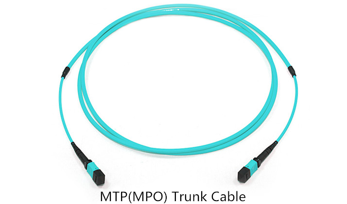
MTP/MPO trunk cables are designed for high density applications which offer excellent benefits in terms of on-site installation time and space saving. Trunk cables serve as a permanent link connecting the MTP/MPO modules to each other.
MTP(MPO) Trunk Cable
MTP/MPO harness Cable in 40GbE/100GbE Migration
As data communication technology migrates from 10GbE to 40GbE and 100GbE, transition from discrete commercial connectors to MTP/MPO connectors is essential. MTP/MPO harness cables are ideal for connecting high speed switches populated with such higher rate transceivers as QSFP+ transceivers to existing 10GbE elements populated with SFP+ modules.
Conclusion
Generally speaking, with its high-density MTP/MPO connectors and harness cables, the MTP/MPO harness cable is suit for high density environment that demands space saving and reduced cable management solutions. Furthermore, supporting various connections from multi-fiber to single-fiber, the MTP/MPO harness cable is an ideal connection to patch panels and data distribution routing.
Originally published at www.fiber-optical-networking.com/
Thursday, September 17, 2015

Important Components in DWDM System

Dense wavelength division multiplexing (DWDM) is one of the most recent and important technologies in the development of fiber optic transmission technology. Its most obvious advantage is the ability to provide potentially unlimited transmission capacity. In a DWDM system, there are four important components, which are optical transmitter/receiver, DWDM Mux/Demux filter, optical add/drop multiplexer (OADM) and optical amplifier. This article will give an introduction to these four components respectively.
Optical Transmitter/Receiver (Transceiver)
As a highly important part in the DWDM system, the optical transmitter/receiver is responsible for providing source signals and receiving signals. Multiple optical transmitters are used as the light sources in a DWDM system. The lasers on the transmit side create pulses of light. Each light pulse has an exact wavelength which shall be precise and stable.
As the development of fiber optic transmission technology, the optical transmitter/receiver has been gradually replaced by the optical transceiver. Optical transceiver is a device comprising both a transmitter and a receiver which are combined and share common circuitry or a single housing. There is another device named transponder used in the DWDM system sometimes. It has the similar principle with the optical transceiver. Both optical transceivers and transponders have the function of optical-electrical-optical (O-E-O) conversion. The main difference between them is that the interface of optical transceivers is serial, while the interface of transponders is parallel.
DWDM Mux/Demux Filters
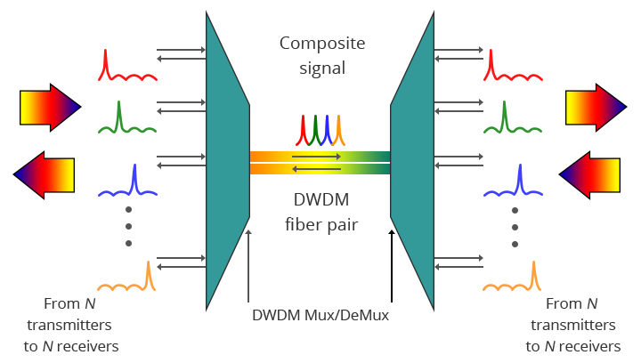
It is known to us that multiple wavelengths created by multiple transmitters operates on different fibers. The role of optical filter (multiplexer filter) is to combine these multiple wavelengths onto one fiber. The output signal of an optical multiplexer is referred to as a composite signal. Then an optical drop filter (demultiplexer) at the receiving end performs the function of separating out all the individual wavelengths of the composite signal to individual fibers. One thing needed to be noted is that the demultiplexing process should be done before the light is detected. The following figure shows a bidirectional DWDM operation. N light pulses of N different wavelengths carried by N different fibers are combined by a DWDM Mux. A DWDM Demux receives the composite signal and separates each of the N component signals and passes each to a fiber.
bidirectional DWDM operation
DWDM OADM
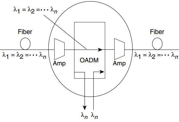
In the DWDM system, there is an area in which multiple wavelengths exist between multiplexing and demultiplexing points. And it is desirable that one or more wavelengths at some point along this span can be added or dropped. The OADM is designed for this function. Rather than combining or separating all wavelengths, the OADM can remove some of the wavelengths and allow the other wavelengths to pass on. The following figure shows the add-drop process of OADM ("Amp" represents for amplification, "λ" represents for wavelength).
the add-drop process of OADM
Optical Amplifier
Since the DWDM system is for long transmission links, the signals must be amplified after a certain fiber length. As a kind of “in-fiber” device, optical amplifier boosts the amplitude or add gain to optical signals passing on a fiber through the way of directly stimulating the photons of the signal with extra energy. Optical amplifier can amplify optical signals across a broad range of wavelengths, which is very important for DWDM system application. The commonly used in-fiber amplifier is erbium-doped fiber amplifier (EDFA).
Continuing to provide the bandwidth for large amounts of data, DWDM is now becoming the basis of all-optical networking with wavelength provisioning and mesh-based protection.
Originally published at www.fiber-optical-networking.com/.