Wednesday, October 14, 2015

Important Components for 40/100G Ethernet Migration

With the growth of bandwidth-intensive applications such as high-performance computing and business continuity, there emerge higher-speed networks of 40/100G Ethernet. And as products become less expensive and more available over time, 40/100G Ethernet will inevitably be commonplace in our daily life. Therefore, it is necessary to create a migration path by installing a structured cabling system that can support the future 40/100G networking needs. In this system, such fiber optic products as MTP/MPO connectors, 40/100G transceivers and 40/100G direct attach cables (DACs) are important components. This article will discuss their roles in 40/100G Ethernet migration respectively.
Since 40/100G Ethernet uses parallel optics technology which requires data transmission across multiple fibers simultaneously, the multi-fiber connectors are needed. MTP/MPO is the designated interface for multi-mode 40/100G Ethernet, and its backward is compatible with legacy 1G/10G applications as well. 40G Ethernet uses a 12 position MTP/MPO connector interface that aligns 12 fibers in a single row. And the 4 leftmost fibers are used to transmit data, the middle 4 fibers are left unused, while the 4 rightmost fibers are used to receive data. 100G Ethernet uses a 24 position MTP/MPO connector with two rows of 12 fibers. And the outermost fibers on either end of the rows are vacant, while 10 fibers in the upper row for transmitting data and the remaining 10 fibers in the lower row for receiving data.
optical lane assignments

40/100G Transceivers
Together with MTP/MPO connectors, 40/100G transceivers are often used (as shown in the above figure). Through the use of plug-and-play, hot-swap transceiver miniaturization, fiber connectivity in higher-speed active equipment is being condensed and simplified. Transceivers used in 40/100G Ethernet migration include 40G QSFP+ transceivers, 100G CFP transceivers and so on. 40G QSFP+ transceivers can support 4x10G modes, which allow new parallel optics active equipment being compatible with existing 10G transceivers. And the electrical connection of a 100G CFP transceiver uses 10x10G lanes in RX (receive) and TX (transmit) direction, supporting both 10x10G and 4x25G variants of 100G interconnects.

40/100G DACs
To save cost, 40/100G DACs are often used in 40/100G Ethernet instead of optical transceivers. Applied to short reach applications, it is a fixed assembly supporting high speed data that uses a small form-factor connector module as an optical transceiver on each end of a length of cable. The modules on each end meet small form-factor standards and have some function of the optical transceivers, meaning that DAC inherits some advantages of the small form-factor module. Thus, sometime there is no need to upgrade the equipment by using a DAC.

To meet the future 40/100G networking needs, the cabling system shall include components that not only support future high-bandwidth applications but also be compliant to 1G and 10G applications and all current and anticipated industry standards. Meeting all these requirements, the above mentioned MTP/MPO connectors, 40/100G transceivers and 40/100G DACs play important roles in migration to 40/100G Ethernet. As a professional supplier of fiber connectivity network solutions, Fiberstore supplies all these fiber optic products and other kinds of products for 40/100G Ethernet migration.

Originally published at www.fiber-optical-networking.com.
Thursday, October 8, 2015

Optical Fiber Access Modes

Optical fiber broadband is a technology that converts electrical signals carrying data to optical signals and sends the optical signals through transparent glass fibers. The signal conversion process is completed through the optical modems installed on both ends of the optical fiber. Among various transmission media for the broadband network, optical fiber is an ideal one, which features in large transmission capacity, high transmission quality, long repeater spacing and low loss.
Optical fiber access technology provides users with high-speed bandwidth of 10 Mbps, 100 Mbps and 1000 Mbps that can be directly connected with the main crunodes of the internet. With high speed access to local area network (LAN) and high speed interconnection with internet, optical fiber access technology is applied mainly to LANs for business groups and intelligent residences. This article will introduce five common access modes of optical fiber.
Optical fiber + Ethernet Access
Ethernet is a kind of technology for LANs and metropolitan area networks (MANs). When the optical fiber is connected with Ethernet, it is necessary to use switch, photoelectric converter and Cat5e.
Applications: residential areas and commercial buildings where generic cabling and system integration for optical fiber access are completed or easy to be implemented.
Optical Fiber + HomePNA Access
HomePNA is an industry standard for home networking over the existing coaxial cables and telephone wiring within homes. To connected optical fiber with the HomePNA, HomePNA switch (Hub) and HomePNA termination equipment (Modem) are important to connect optical fiber to the HomePNA.
Applications: residential areas and hotel buildings where generic cabling and system integration are undone or inconvenient to be done.
Optical Fiber + VDSL Access
Very-high-bit-rate digital subscriber loop (VDSL) is a technology providing data transmission over a single flat untwisted or twisted pair of copper wires and on coaxial cable. VDSL switch and VDSL termination equipment are essential to connect optical fiber with VDSL.
Applications: residential areas and hotel buildings where generic cabling and system integration are undone or inconvenient to be done.
FTTx + LAN Access
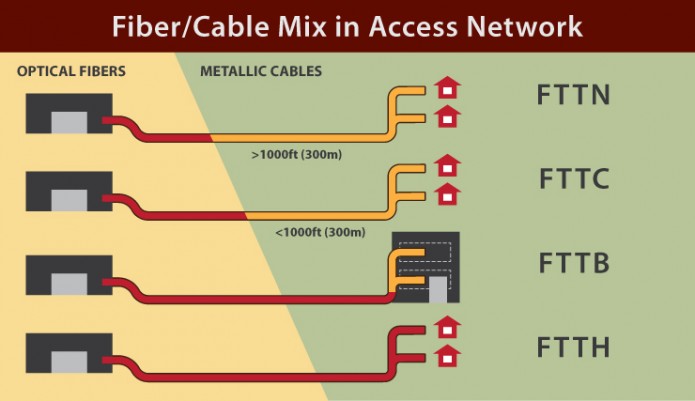
FTTx stands for fiber to the x, where x stands for home, curb, neighborhood, business, etc (as shown in the following figure). LAN refers to local area network. FTTx+LAN access aims at Gigabit Ethernet for the community, fast Ethernet for the building and 10 Mpbs Ethernet for the user.
fiber cable mix in access network
Applications: it is mainly applied to concentrated residential areas, enterprises and public institutions and universities and colleges. In FTTx+LAN, generic cabling is done in residential areas, high-class offices and student dormitories and teacher dormitories in universities and colleges.
Optical Fiber Access
Optical fiber access with transmission bandwidth from 2 Mbps to 155 Mbps is designed for enterprises and public institutions or groups who need the independent optical fiber-optic high-speed Internet. Since the bandwidth for upload and download is high, optical fiber access is suitable for such activities as remote instruction, tele-medicine and video conference.
Applications: it is applied to concentrated residential areas, communities and offices where generic cabling is done or easy to be implemented. Furthermore, it also applied to enterprises and public institutions or groups who need the independent optical fiber-optic high-speed Internet.
Optical fiber access is expanding due to the demand for broadband in consumer environment. Thus, products such as switches, photoelectric converters and transceivers used in optical fiber access are various in the market. As a professional supplier of optical communication products, Fiberstore supplies many kinds of products used in optical fiber access. Customers may choose the proper optical fiber optic access mode and optical fiber products according to their needs.
Originally published at www.fiber-optical-networking.com/.

Tuesday, September 29, 2015

Technologies Used in Multiplexing

Sending email is a commonplace occurrence in our daily life. When you send an email to a friend in another city, it will firstly join up with other messages being transmitted in your city, and then get dropped off at the correct destination in the correct city. How do all of these messages get to join together and be transmitted without getting mixed up? This process is achieved through the use of multiplmexing technology, which is a method that combines multiple analog message signals or digital data streams into one signal over a shared medium. Actually, multiplexing is widely used in many telecommunications applications. This article will introduce multiplexing technology from the aspect of common technologies used in multiplexing.
Optical multiplexing filter is an essential component in multiplexing technology, which is a physical device that combines each wavelength with other wavelengths (as shown in the following figure). Many technologies are applied in multiplexing, including thin-film filter (TFF), fiber bragg grating (FBG), arrayed waveguide grating (AWG) and interleaver, periodic filter, and frequency slicer.
filter
TFF
Optical TFF typically consists of multiple alternating layers of high- and low-refractive-index material deposited on a glass or polymer substrate. This substrate is made to let only photons of a specific wavelength pass through, while all others are reflected.
FBG
A bragg grating is made of a small section of fiber that has been modified by exposure to ultraviolet radiation to create periodic variations in the refractive index of the fiber. And the process of creating periodic variations will generate wavelength-specific dielectric mirrors. Thus, the FBG can reflect particular wavelengths of light and transmit all others.
AWG
AWG devices can multiplex a large number of wavelengths into a single optical fiber. These devices are designed on the fundamental principle of optics that light waves of different wavelengths interfere linearly with each other. That’ to say, if each channel in an optical communication network makes use of light of a slightly different wavelength, then the light from a large number of these channels can be carried by a single optical fiber.
Interleaver, Periodic filter, and Frequency Slicer
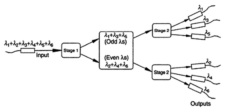
Interleaver, periodic filter and frequency slicer are often used together to perform the function of multiplexing. The following figure shows how interleaver, periodic filter and frequency slicer work together to make a multiplexer device. Periodic filter is in stage 1, which is an AWG. Stage 2 represents the frequency slicer which is another AWG. The interleaver is at the output part, which is provided by six bragg gratings. Six wavelengths (λ) are received at stage 1 which breaks the wavelengths down into odd and even wavelengths. Then the odd and even wavelengths go to stage 2 respectively. Finally, they are delivered by the interleaver in the form of six discrete, interference-free optical channels.
interleaver, periodic filter and frequency slicer
All in all, the usual goal of multiplexing is to enable signals to be transmitted more efficiently over a given communication channel rather than save bandwidth. Nowadays, the most popular multiplexing technology is wavelength division multiplex (WDM), which can be divided into coarse wavelength division multiplexing (CWDM) and dense wavelength division multiplexing (DWDM). It is hoped that multiplexing technology would offer significant gains in bandwidth efficiency.
Originally published at www.fiber-optical-networking.com/

Tuesday, September 22, 2015

Things You Need to Know About MTP/MPO Harness Cable

MTP/MPO harness cable, also called MTP/MPO breakout cable or MTP/MPO fan-out cable, is a fiber optic cable terminated with MTP/MPO connectors on one end and MTP/MPO/LC/FC/SC/ST/MTRJ connectors (generally MTP to LC) on the other end (as shown in the following figure). In addition to its definition, here are something you also need to know about MTP/MPO harness cable.
MTP(MPO) harnesses cable
What Is MTP/MPO Connector
As a kind of multi-fiber connector, the MTP/MPO connector is most commonly used for 12 or 24 fibers in a single connector pushing up to and beyond 100Gbps data transmission. Thus it satisfies the huge demand for more bandwidth and more space efficiency of data centers and ever-expanding server clusters. MTP/MPO connectors are paving the way for increased data transmission speeds and rack density.
Though MTP and MPO are literally different from each other, they are often used interchangeably. The MPO connector is a multi-fiber connector that is defined by IEC-61754-7, and the MTP is a registered trade mark of US Conec (a leader in providing passive components for high density optical interconnects), which identifies a specific brand of the MPO style connector.
Common Types of MTP/MPO Harness Cable
As mentioned above, the connectors on each end of the fiber cable may be the same or not. Thus, the MTP/MPO harness cable is usually divided into MPO/MTP-MPO/MTP harness cable, MPO/MTP-Secure Keyed LC harness cable and MPO/MTP-Standard LC/FC/SC/ST/MTRJ harness cable. In the MPO/MTP-Secure Keyed LC harness cable, the secure keyed LC connector provides a quick, simple termination method, featuring a pre-installed cleaved fiber with an index-matching splice element, and a precision factory pre-polished zirconia ceramic ferrule.
Differences Between MTP/MPO Harness Cable and MTP/MPO Trunk Cable
MTP/MPO harness cables and MTP/MPO trunk cables are two common kinds of MTP/MPO fiber cables. They differ from each other in such aspects as function and application.
MTP/MPO harness cables are designed for high density applications requiring high performance and speedy installation. Harness cables provide a transition from multi-fiber cables to individual fibers or duplex connectors. Therefore, they can meet a variety of fiber cabling requirements.
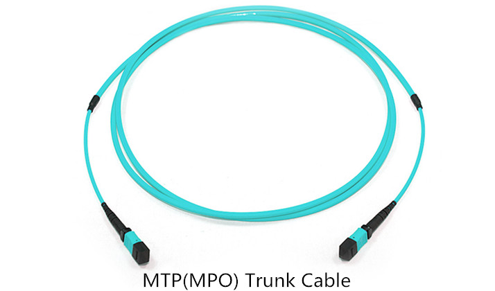
MTP/MPO trunk cables are designed for high density applications which offer excellent benefits in terms of on-site installation time and space saving. Trunk cables serve as a permanent link connecting the MTP/MPO modules to each other.
MTP(MPO) Trunk Cable
MTP/MPO harness Cable in 40GbE/100GbE Migration
As data communication technology migrates from 10GbE to 40GbE and 100GbE, transition from discrete commercial connectors to MTP/MPO connectors is essential. MTP/MPO harness cables are ideal for connecting high speed switches populated with such higher rate transceivers as QSFP+ transceivers to existing 10GbE elements populated with SFP+ modules.
Conclusion
Generally speaking, with its high-density MTP/MPO connectors and harness cables, the MTP/MPO harness cable is suit for high density environment that demands space saving and reduced cable management solutions. Furthermore, supporting various connections from multi-fiber to single-fiber, the MTP/MPO harness cable is an ideal connection to patch panels and data distribution routing.
Originally published at www.fiber-optical-networking.com/

Thursday, September 17, 2015

Important Components in DWDM System

Dense wavelength division multiplexing (DWDM) is one of the most recent and important technologies in the development of fiber optic transmission technology. Its most obvious advantage is the ability to provide potentially unlimited transmission capacity. In a DWDM system, there are four important components, which are optical transmitter/receiver, DWDM Mux/Demux filter, optical add/drop multiplexer (OADM) and optical amplifier. This article will give an introduction to these four components respectively.
Optical Transmitter/Receiver (Transceiver)
As a highly important part in the DWDM system, the optical transmitter/receiver is responsible for providing source signals and receiving signals. Multiple optical transmitters are used as the light sources in a DWDM system. The lasers on the transmit side create pulses of light. Each light pulse has an exact wavelength which shall be precise and stable.
As the development of fiber optic transmission technology, the optical transmitter/receiver has been gradually replaced by the optical transceiver. Optical transceiver is a device comprising both a transmitter and a receiver which are combined and share common circuitry or a single housing. There is another device named transponder used in the DWDM system sometimes. It has the similar principle with the optical transceiver. Both optical transceivers and transponders have the function of optical-electrical-optical (O-E-O) conversion. The main difference between them is that the interface of optical transceivers is serial, while the interface of transponders is parallel.
DWDM Mux/Demux Filters
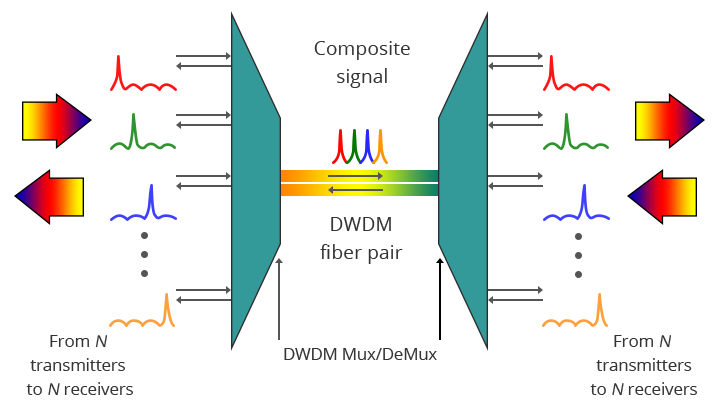
It is known to us that multiple wavelengths created by multiple transmitters operates on different fibers. The role of optical filter (multiplexer filter) is to combine these multiple wavelengths onto one fiber. The output signal of an optical multiplexer is referred to as a composite signal. Then an optical drop filter (demultiplexer) at the receiving end performs the function of separating out all the individual wavelengths of the composite signal to individual fibers. One thing needed to be noted is that the demultiplexing process should be done before the light is detected. The following figure shows a bidirectional DWDM operation. N light pulses of N different wavelengths carried by N different fibers are combined by a DWDM Mux. A DWDM Demux receives the composite signal and separates each of the N component signals and passes each to a fiber.
bidirectional DWDM operation
DWDM OADM
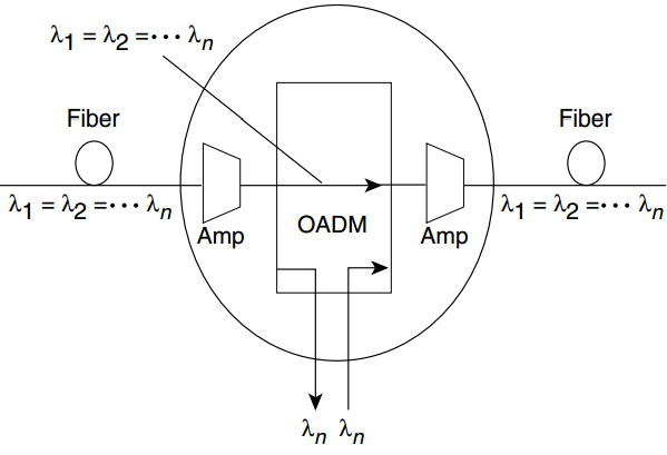
In the DWDM system, there is an area in which multiple wavelengths exist between multiplexing and demultiplexing points. And it is desirable that one or more wavelengths at some point along this span can be added or dropped. The OADM is designed for this function. Rather than combining or separating all wavelengths, the OADM can remove some of the wavelengths and allow the other wavelengths to pass on. The following figure shows the add-drop process of OADM ("Amp" represents for amplification, "λ" represents for wavelength).
the add-drop process of OADM
Optical Amplifier
Since the DWDM system is for long transmission links, the signals must be amplified after a certain fiber length. As a kind of “in-fiber” device, optical amplifier boosts the amplitude or add gain to optical signals passing on a fiber through the way of directly stimulating the photons of the signal with extra energy. Optical amplifier can amplify optical signals across a broad range of wavelengths, which is very important for DWDM system application. The commonly used in-fiber amplifier is erbium-doped fiber amplifier (EDFA).
Continuing to provide the bandwidth for large amounts of data, DWDM is now becoming the basis of all-optical networking with wavelength provisioning and mesh-based protection.
Originally published at www.fiber-optical-networking.com/.

Friday, August 28, 2015

1000BASE SFP Transceivers Used in Gigabit Ethernet

Gigabit Ethernet, which is standardized by the IEEE as the 802.3z standard, is a term describing various technologies for transmitting Ethernet frames at a rate of a Gigabit per second. The 1000BASE SFP transceiver is an important part in Gigabit Ethernet applications, which is a hot-swappable input/output device that plugs into a Gigabit Ethernet port/slot, linking the port with the network. There is a number of 1000BASE SFP transceivers that are available in accordance with the customer application and distance capability required.

Depending on the cable material, Gigabit Ethernet can be classified into fiber-based Gigabit Ethernet and copper-based Gigabit Ethernet. Different 1000BASE SFP transceivers may used in different kinds Gigabit Ethernet.

1000BASE SFP Transceivers in Fiber-based Gigabit Ethernet
In fiber-based Gigabit Ethernet, 1000BASE-X is used in industry to refer to Gigabit Ethernet transmission over fiber. 1000BASE-X is a group of standards for Ethernet physical layer standards, including 1000BASE-SX, 1000BASE-LX, 1000BASE-LX10, 1000BASE-BX10 or the non-standard 1000BASE-EX and 1000BASE-ZX implementations. Different 1000BASE SFP transceivers may be used in different standards.
  • 1000BASE-SX SFP Transceiver for 1000BASE-SX
1000BASE-SX operates over multi-mode fiber using an 850nm laser. 1000BASE-SX SFP transceiver is a high performance module used for 1000BASE-SX. It operates on legacy multi-mode fiber links up to 550m and on Fiber Distributed Data Interface (FDDI)-grade multi-mode fibers up to 220m, supporting up to 1km over laser-optimized multi-mode fiber cable.
1000BASE-SX SFP
  • 1000BASE SFP Transceiver for 1000BASE-LX
1000BASE-LX represents the long wave laser version of Gigabit Ethernet over fiber, which can operate over single-mode or multi-mode fiber. The 1000BASE-LX SFP transceiver operates on standard single-mode fiber-optic link spans of up to 10km and up to 550m on any multi-mode fibers.
1000BASE-LX SFP
  • 1000BASE SFP Transceiver for 1000BASE-LX10
1000BASE-LX10 is very similar to 1000BASE-LX, but it achieves longer distances over a pair of single-mode fiber. The 1000BASE-LX10 SFP transceiver can operate over single-mode fiber links up to 10km.
  • 1000BASE SFP Transceiver for 1000BASE-BX10
1000BASE-BX10 is capable of up to 10 km over a single strand of single-mode fiber. The 1000BASE-BX10 SFP Transceivers operate on a single strand of standard single-mode fiber.
  • 1000BASE SFP Transceiver for 1000BASE-EX
1000BASE-EX a industry accepted term to refer to Gigabit Ethernet transmission. The 1000BASE-EX SFP transceivers operate on standard single-mode fiber-optic link spans of up to 40 km in length.
  • 1000BASE SFP Transceiver for 1000BASE-ZX
Through the use of single-mode fiber and a long-wavelength laser (1550nm), 1000BASE-ZX obtains a span line of 70km. Operating on standard single-mode fiber-optic link spans of up to approximately 70km in length, the 1000BASE-ZX SFP transceivers are used in long-reach single-mode fibers.

1000BASE SFP Transceivers in Copper-based Gigabit Ethernet
In copper-based Gigabit Ethernet, 1000BASE-CX, 1000BASE-KX, 1000BASE-T and 1000BASE-TX are four standards for Gigabit Ethernet over copper wiring. Similarly, various 1000BASE SFP transceivers are used in these four standard.
  • 1000BASE SFP Transceiver for 1000BASE-CX
1000BASE-CX represents the initial IEEE standard for Gigabit Ethernet over copper cabling using 150Ω balanced shielded twisted-pair wire. The 1000BASE-CX SFP transceiver is intended for short cable runs over copper cabling.
  • 1000BASE SFP Transceiver for 1000BASE-KX
1000BASE-KX is part of the IEEE 802.3ap standard for Ethernet Operation over Electrical Backplanes. Since it uses electrical signaling speed rather than optical signaling, there is no SFP Transceiver for this standard.
  • 1000BASE SFP Transceiver for 1000BASE-T
1000BASE-T defines the transmission of Gigabit Ethernet over four pairs of cable. The 1000BASE-T SFP transceiver operates on standard Category 5 unshielded twisted-pair copper cabling of link lengths up to 100m.
1000BASE-T SFP
  • 1000BASE SFP Transceiver for 1000BASE-TX
1000BASE-TX is similar to 1000BASE-T but uses two pairs of wires rather than four for data transmission. Theoretically, it is design to reduce the cost of the required electronics by only using two unidirectional pairs in each direction instead of 4 bidirectional. But this is proved to be a commercial failure. Therefore, 1000BASE-TX SFP Transceiver is uncommon.

As Gigabit Ethernet has been demonstrated to be a viable solution for increased bandwidth requirements for growing networks, the market is flooded with various 1000BASE SFP transceivers. Fiberstore supplies many kinds of 1000BASE SFP transceivers including the aforesaid 1000BASE-SX SFP, 1000BASE-LX SFP, 1000BASE-ZX SFP, 1000BASE-LH SFP and 1000BASE-T SFP transceivers and so on.

Monday, August 3, 2015

Things to Know Before Selecting CWDM SFP Transceivers

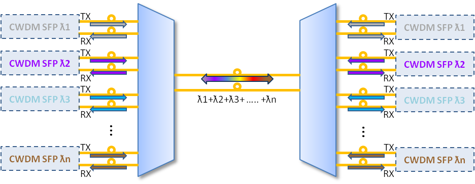
As an extension of wavelength division multiplexing (WDM), coarse wavelength division multiplexing (CWDM) is a technology that multiplexes a number of optical carrier signals onto a single optical fiber through the use of different wavelengths (i.e., colors) of laser light. A CWDM SFP (Small Form-factor Pluggable) is on the SFP transceivers or socket switch or router port (as shown below). In the following figure, TX represents transmit, RX represents receive. Being a kind of compact optical transceiver, CWDM SFP transceivers are widely used in optical communications for both telecommunication and data communication. It is designed for operations in Metro Access Rings and Point-to-Point networks using Synchronous Optical Network (SONET), SDH (Synchronous Digital Hierarchy), Gigabit Ethernet and Fiber Channel networking equipment.
CWDM SFP
Three Components of CWDM SFP Transceivers
The CWDM SFP transceiver is consist of an un-cooled CWDM Distributed Feed Back (DFB) laser transmitter, a PIN photodiode integrated with a Trans-impedance Preamplifier (TIA) and a Microprogrammed Control Unit (MCU). The DFB laser used in the CWDM SFP transceiver transmitter is a 18 CWDM DFB wavelengths laser. It is well suited for high capacity reverse traffic. Obeying the standard diode equation for low frequency signals, The PIN photodiode has a 80km transmission distance. And the MCU is a high-speed, executive, input-output (I/O) processor and interrupt handler for the NRL Signal Processing Element (SPE).
Advantages of CWDM SFP transceivers
Using existing fiber connections efficiently through the adoption of active wavelength multiplexing, CWDM SFP transceivers have improved the designs of telecommunications devices and other technologies. Here are some advantages of CWDM SFP transceivers:
  • Scalability and Flexibility—CWDM SFP transceivers can support multiple channels. It means that more channels can be activated as demand increases. CWDM SFP transceivers have a wide variety of network configurations that range from the meshed-ring configurations to the multi-channel point-to-point. In point-to-point configurations, the two endpoints will connect directly through a fiber link, allowing users to add or delete as many as eight channels at a time.
  • Low Risks in Investment—Most CDWM SFP Transceivers have a low failure rate, which is less likely to be the reason why the user’s solution fails. It helps enterprises increase the bandwidth of the Gigabit Ethernet optical infrastructure without adding any additional fiber strands and can also be used in conjunction with other SFP devices on the same platform. Thus the user will be able to re-invest the capital saved by avoiding prematurely failed devices.
Selecting a Right CWDM SFP Transceiver
There are many kinds of CDWM SFP Transceivers in the market. Their wavelengths are available from 1270 nm to 1610 nm, with each step 20 nm. Different CDWM SFP Transceivers have different color codes, distances, date rates and laser operating wavelengths. For example, the CWDM-SFP-1470, which is colored gray, is one of Cisco CWDM SFP. It is a CWDM SFP transceiver that rates for distances up to 80 km and a maximum bandwidth of 1Gbps, operating at 1470nm wavelength. Customers may choose a CWDM SFP transceiver in accordance with their actual needs.
Cisco CWDM-SFP-1470
Applied to the access layer of Metropolitan Area Network (MAN), The CWDM SFP is a low-cost WDM transmission technology. Fiberstore provides the aforesaid CWDM-SFP-1470 and other types of CWDM SFP Transceivers, which are convenient and cost-effective solution for the adoption of Gigabit Ethernet and Fiber Channel (FC) in campus, data center, and metropolitan-area access networks.

Thursday, July 30, 2015

Different Technologies Used in DWDM Multiplexer

Dense wavelength division multiplexing (DWDM) is an advancing fiber-optic transmission technology which combines multiple optical channels at different light wavelengths and then transmits them over the same optical fiber. Theoretically, the DWDM technology can multiplex hundreds and even thousands of separate wavelengths into a single optical fiber. To achieve this goal, the DWDM multiplexer is one of the most important parts needing to be improved. This article will discuss several commonly used technologies in the wavelength-selective mechanism of the DWDM multiplexer.
Simplex-Directional-Transmission-Dwdm-Mux-Demux
Key Optical Parameters of the DWDM Multiplexer
To better understand those technologies, we need to have a basic knowledge of the DWDM multiplexer’s main optical parameters which are center frequency, insertion loss, pass-band and cross talk.
Center frequency is usually defined as either the arithmetic mean or the geometric mean of the lower cutoff frequency and the upper cutoff frequency of a band-pass system or a band-stop system. Insertion loss is the input-to-output power loss caused by the insertion of a device in a transmission line or optical fiber. A pass-band is the portion of the frequency spectrum that is transmitted (with minimum relative loss or maximum relative gain) by some filtering device. Wider and flatter pass-band makes the system more tolerable to wavelength drift of the laser transmitter. The energy leakage from adjacent and nonadjacent channels in the DWDM system is defined as cross talk.

Technologies Used in the Wavelength-selective Mechanism of the DWDM Multiplexer
Interference filter, bulk grating, array waveguide grating (AWG), and Mach-Zehnder (MZ) interferometer are the four common-used technologies in the DWDM multiplexer.

Interference filter
Consisting of multiple thin layers of dielectric material having different refractive indices, the interference filter reflects one or more spectral bands or lines and transmits others. The dielectric thin-film filter is one of the most popular technologies use to make the DWDM multiplexer.

bulk grating
Being a classical optics technology that has been in existence for over 100 years, bulk grating is now one of the newest technological forerunners in the field of DWDM.


AWG
As the AWG is capable of multiplexing a large number of wavelengths into a single optical fiber, it is commonly used as optical (de)multiplexers in wavelength division multiplexed (WDM) systems, which considerably increases the transmission capacity of optical networks.

MZ interferometer
As a basic interference device, the MZ interferometer is consist of two couplers connected by two waveguides of different length. It is widely used in various fibre-optic communications applications.

A high-performance DWDM multiplexer should have small polarization-dependent loss (PDL), low polarization mode dispersion (PMD), and the same performance under hostile environment temperature. A series of DWDM MUX/DEMUX modules are provided by Fiberstore, which is with as more as 96 channels (50GHz, 100GHz, or 200GHz spaced) in simplex or duplex configurations. All the DWDM modules are available with three types of packaging: ABS Pigtailed Box, Rack Chassis and LGX Cassette.

Tuesday, July 28, 2015

What Is CWDM SFP Transceiver

Being a kind of compact optical transceiver, the CWDM SFP Transceiver is widely used in optical communications for both telecommunication and data communication. Basing on the SFP form factor which is a MSA standard build, it is designed for operations in Metro Access Rings and Point-to-Point networks using Synchronous Optical Network (SONET), SDH (Synchronous Digital Hierarchy), Gigabit Ethernet and Fibre Channel networking equipment.
CWDM SFP
The CWDM SFP Transceiver is a cost effective module with high performance, supporting data-rate of 1.25 Gbps and 80km transmission distance. It has a specific laser which emits a “color” defined in the CWDM International Telecommunication Union (ITU) grid that is defined from 1270 to 1610nm and has steps of 20nm. Thus its available wavelength includes 1270nm, 1290nm, 1310nm, 1330nm, 1350nm, 1370nm, 1390nm, 1410nm, 1430nm, 1450nm, 1470nm, 1490nm, 1510nm, 1530nm, 1550nm, 1570nm, 1590nm and 1610nm.
The CWDM SFP transceiver is consist of an uncooled CWDM Distributed Feed Back (DFB) laser transmitter, a Pin photodiode integrated with a Trans-impedance Preamplifier (TIA) and a Microprogrammed Control Unit (MCU). The DFB laser used in the CWDM SFP transceiver transmitter, which is a 18 CWDM DFB wavelengths laser, is well suited for high capacity reverse traffic. Obeying the standard diode equation for low frequency signals, The PIN photodiode has a 80km transmission distance. And the MCU is a high-speed, executive, input-output (I/O) processor and interrupt handler for the Network Restructuring Language (NRL) Signal Processing Element (SPE).
The CWDM SFP is a hot-swappable, transceiver component that can be plugged into a SFP-compatible uplink port. And each SFP port must match the wavelength specifications on the other end of the cable which must not exceed the stipulated cable length for reliable communications.
Applied to the access layer of Metropolitan Area Network (MAN), The CWDM SFP is a low-cost Wavelength Division Multiplex (WDM) transmission technology. Adopting the CWDM technology, it can combine optical signals with different wavelength together and transmit them with one fiber strand. It can largely save the fiber resources. The CWDM SFP allows enterprise companies and service providers to provide scalable and easy-to-deploy Gigabit Ethernet and Fibre Channel services in their networks, enabling the flexible design of highly available, multiservice networks.
Fiberstore’s CWDM SFP transceiver provides a convenient and cost-effective solution for the adoption of Gigabit Ethernet and Fiber Channel (FC) in campus, data-center, and metropolitan-area access networks. With its maximum optical budget of 41dB, Fiberstore CWDM SFP modules support data rates from 100 Mbps up to 4.25 Gbps.

Monday, July 27, 2015

A Brief Introduction to CWDM Mux/Demux

CWDM Mux/Demux is the short name for Coarse Wavelength Divison Multiplexer/Demultiplexer Module, which is a flexible, low-cost solution enabling the expansion of existing fiber capacity. It is based on dielectric thin-film technology designed for integration in low cost Metro and Access networks. Combining with highly reliable passive optics certified for environmentally hardened applications, the CWDM Mux/Demux enables the operator to make full use of available fiber bandwidth in local loop and enterprise architectures. This module can either combine (added) or separated (dropped) 4, 8 16 or 18 channels .


What is Mux/Demux
The Mux is a module that makes it possible to share several signals in one device or resource such as an analog-to-digital converter (A/D converter) or one communication line, instead of having one device per input signal. A Mux is also called a data selector, which is mainly used to increase the amount of data that can be sent over the network within a certain amount of time and bandwidth.
On the contrary, the Demux, which is connected to the single input, takes a single input signal and selecting one of many data-output-lines. A complementary Demux is often used with a Mux on the receiving end.

How does CWDM Mux/Demux work
Through the use of Mux, several optical channels of different wavelengths can be combined, allowing multiple services to be transmitted together via fiber without interference. This can be possible for the reason that different light colours (wavelengths) do not affect each other. For transmission, light colours are multiplexed onto an fiber using a wavelength-specific filter (multiplexing). At the other (receiving) end of the line, the wavelengths are divided or demultiplexed again by the Demux. Hence, any transmission line consists of a multiplexer and a demultiplexer.
Being a universal device capable of combining nine optical signals into a fiber pair, the CWDM Mux/Demux is designed to support a broad range of architectures, ranging from scalable point-to-point links to two fiber-protected rings.

What are the features of CWDM Mux/Demux
First of all, as a passive CWDM optical mux/demux design, the CWDM Mux/Demux has a long transmission distance coverage of multiple signals on a single fiber strand. Secondly, it can support various types of signals such as 3Gbps/HD/SD, AES, DVB-ASI, Ethernet, etc. Furthermore, its ambient operating temperature is from -40°C to 85°C. In another word, CWDM Mux/Demux is suitable for outside plant applications. Last but not least, it requires no powering because of thermally stable passive optics.

The CWDM MUX/DEMUX modules are used to combine and split the multi-wavelength optical signals of CWDM networks. Fiberstore provides a series of CWDM MUX/DEMUX modules with as more as 18 channels (20nm spaced) in simplex or duplex configurations. All the CWDM modules are available with three types of packaging: ABS Pigtailed Box, Rack Chassis and LGX Cassette.


Thursday, July 23, 2015

Differences between CWDM and DWDM

Coarse Wavelength Division Multiplexing (CWDM) and Dense WaveLength Division Multiplexing (DWDM) are two kinds of wavelength-division multiplexing (WDM) which is a technology multiplexing a number of optical carrier signals onto a single optical fiber by using different wave lengths of laser light. Seeing from their development, DWDM came well before CWDM. DWDM appeared only after a booming telecommunications market, driving prices to affordable lows. Whereas CWDM breaks the spectrum into big chunks. Here is some information related to the differences between CWDM and DWDM.
 CWDMDWDM
Definitions
CWDM is a method of combining multiple signals on laser beams at various wavelengths for transmission along fiber optic cables. Its WDM system has less than 8 active wavelengths per optical fiber.
DWDM is a fiber-optic transmission technique that employs light wavelengths to transmit data parallel-by-bit or serial-by character. Its WDM system has more than 8 active wavelengths per optical fiber.

Capacities
Each CWDM wavelength, which can be expanded to 10Gbps support, typically supports up to 2.5Gbps. This transfer rate is sufficient to support GbE, Fast Ethernet or 1/2/4/8/10G FC, STM-1/STM-4/STM-16 / OC3/OC12/OC48 and other protocols. However, since the optical amplifiers cannot be used due to the large spacing between channels, the CWDM is typically deployed at networks up to 80Km.
Providing up to 96 wavelengths (at 50GHz) of mixed service types, the DWDM systems can transport to distances up to 3000 km through the deployment of amplifiers and dispersion compensators, which increases the fiber capacity by a factor of x100. Today’s DWDM solution is often embedded with Reconfigurable Optical Add Drop Multiplexer (ROADM). The ROADM enables the building of flexible remotely managed infrastructure in which any wavelength can be added or dropped at any site.

prices
The function of CWDM is to help carriers make the best of their network capacity in the regional, metro and access network sectors. Comparing with DWDM, CWDM supports fewer wavelengths; but it is much cheaper than DWDM. Thus CWDM is the perfect choice for those areas having average traffic growth projections.
Since the laser of DWDM is more precise and stable, it tends to be more expensive at the sub-10G rates. However, for 10G service rates, it is a more appropriate solution,which provides large capacity data transport and connectivity over long distances at affordable costs.

Filters
Due to fewer number of layers in the filter design, the filter of CWDM is inherently less expensive to make than that DWDM. Typically, there are over 100 layers required for a 200 GHz filter design as used in metro DWDM products, where there are only 50 layers in a 20 nm filter used in Metro CWDM products. The result is shorter manufacturing time, less materials and higher manufacturing yields for CWDM filters. As a result, CWDM filter costs are generally less than 50 percent of the cost of comparable DWDM filters.

CWDM networks use CWDM modules such as CWDM MUX/DEMUX and CWDM OADM. While DWDM MUX/DEMUX and DWDM OADM are used in DWDM networks. A series of WDM modules are provided in Fiberstore, which enable the expansion of existing fiber capacity.

What Is Optical Transceiver

What Is Optical Transceiver
As a central component of optical communication, optical transceiver is a kind of optical-electric/electric-optical converter. It is also called fiber optic transmitter and receiver. An optical transceiver consists of a transmitter on one end of a fiber and a receiver on the other end. The transmitter end takes in and converts the electrical signal into light, after the optical fiber transmission in the fiber cable plant, the receiver end again converts the light signal into electrical signal. Both the receiver and the transmitter ends have their own circuitry and can handle transmissions in both directions.
single-mode optical transceiver
The structure of optical transceiver
Optical transmitter: since the sources used for fiber optic transmitters need to be at the correct wavelength, be able to be modulated fast enough to transmit data and be efficiently coupled into fiber, LEDs, fabry-perot (FP) lasers, distributed feedback (DFB) lasers and vertical cavity surface-emitting lasers (VCSELs) are the four commonly used types of sources. Thought these decvices all convert electrical signals into optical signals, they are quite different from each other.
Optical receiver: the optical receiver uses semiconductor detectors (photodiodes or phodetectors) to convert optical signals to electrical signals. Silicon photodiodes are used for short wavelength links (650 for plastic optical fiber and 850 for glass MM fiber). Long wavelength systems usually use indium gallium arsenide (InGaAs) detectors as they have lower noise than germanium which allows for more sensitive receivers. Very high speed systems sometimes use avalanche photodiodes (APDs) that are biased at high voltage to create gain in the photodiode.
The performance of optical transceiver
Just as with copper wire or radio transmission, the performance of the optical data link can be determined by how well the reconverted electrical signal out of the receiver matches the input to the transmitter. The discussion of performance on datalinks applies directly to transceivers which supply the optical to electrical conversion.
Every manufacturer of optical transceivers specifies their product for receiver sensitivity (perhaps a minimum power required) and minimum power coupled into the fiber from the source. Those specifications will end up being the datalink specifications on the final product used in the field.
All datalinks are limited by the power budget of the link. The power budget is the difference between the output power of the transmitter and the input power requirements of the receiver. The receiver has an operating range determined by the signal-to-noise ratio (S/N) in the receiver. The S/N ratio is generally quoted for analog links while the bit-error-rate (BER) is used for digital links. BER is practically an inverse function of S/N.
Three primary types of optical transceiver
There are many different kinds of optical transceivers that can be used in telecommunications applications. The different specs and designs are widely used to meet the changing needs of designers. The small form-factor (SFP), the small form-factor pluggable (SFP+) and the XFP transceiver are the three primary kinds. SFP is available for designers to use in various applications. SFP+ , which is an enhanced version of an SFP, is designed to support data rates up to 10 Gbit/s. While the XFP transceiver can operating at wavelengths of 850nm, 1310nm, and 1550nm, which are capable of operating at a single wavelength.

Wednesday, July 22, 2015

How to Select A Right SFP Transceiver

The small form-factor pluggable (SFP) transceiver is also called mini Gigabit Interface Converter (MINI-GBIC) module due to its smaller size and is the second generation product after the standardized pluggable optical module GBIC. It is a compact, “hot-pluggable” optical transceiver used in optical communications for both telecommunication and data communications application. Nowadays SFP transceivers are being more and more widely used for bi-directional transmission of data between an electrical interface and an optical data link. And SFP transceivers are available with a variety of transmitter and receiver types. Here are some tips for users to select their appropriate SFP tansceiver.

According to different types of optical fiber, SFP transceiver can be divided into the following categories:

1) For multi-mode fiber, with black or beige extraction lever
Only one type of SFP transceiver is available, whose specs is SX-850 nm, for a maximum of 550 m at 1.25 Gbit/s (Gigabit Ethernet) or 150m at 4.25 Gbit/s (fiber Channel).

2) for single-mode fiber, with blue extraction lever
There are many kinds of SFP transceiver available for this type of fiber. For example:
① LX-1310 nm, for distances up to 10 km.
②BX-1490 nm/1310 nm, Single Fiber Bi-Directional Gigabit SFP Transceivers, paired as BS-U and BS-D for Uplink and Downlink respectively, also for distances up to 10 km 1550 nm 40 km (XD), 80 km (ZX), 120 km (EX or EZX).
③Coarse Wavelength Division Multiplexing (CWDM) and Dense WaveLength Division Multiplexing (DWDM) transceivers at various wavelengths achieving various maximum distances.

3) for copper twisted pair cabling
1000BASE-T SFP Transceiver Modules are available, which incorporate significant interface circuitry and can only be used for Gigabit Ethernet, as that is the interface they implement. They are not compatible with (or rather: do not have equivalents for) fiber channel or SONET.

According to the wavelength of SFP transceiver, users can select an appropriate one among 850 nm/1310 nm/1550 nm/1490 nm/1530nm/1610 nm. To be specific, the 850nm wavelength is SFP multimode, and the transmission distance is 2 km below. While the 1310/1550 nm is SFP single-mode, and the transmission distance is longer than 2 km. In the market, the prices of 850 nm/1310 nm/1550 nm SFP transceiver are relatively cheaper than that of the other three.

The SFP transceiver modules are designed to support Synchronous Optical Network (SONET)/Synchronous Digital Hierarchy (SDH), Fast Ethernet, Gigabit Ethernet, fiber Channel and other communications standards. By choosing the appropriate SFP transceiver module, the same electrical port on the switch can connect to fibers of different types (multimode or singlemode) and different wavelengths. Fiberstore manufactures and supplies a complete range of SFP transceiver modules which can be Customized. In addition, all of its SFP transceiver modules come with a lifetime advance replacement warranty and are 100% functionally tested.